BSc Project
2025-05-25
Source: bsc_project
Summary
My bachelor's project, done in spring 2025 at Linköping University as a joint Electronics Design (ED) / Communication, Transportation and Society (KTS) course (TNE107/TNK132), with a team of seven. The brief, from a fictional client, was to build an Automated Guided Vehicle (AGV) that could autonomously map an unknown 5.3 x 3.5 m area, then drive out to a set of visit points in it and back, without colliding with obstacles — mapping and delivery each targeted at around five minutes. The ED half of the team (myself included) designed and built the vehicle itself: two custom PCBs, sensor integration, and all embedded software. The KTS half built the overhead control system (ÖS) — a Java desktop application that received the AGV's telemetry over Bluetooth, ran Dijkstra's algorithm for route planning, and sent back drive commands.
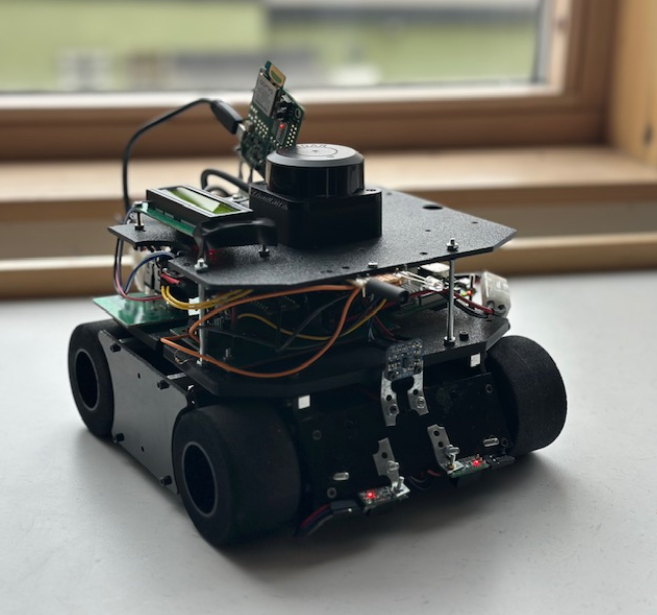
I was one of two who designed the AGV's power/motor-driver PCBs early on, then moved into writing essentially all of its embedded software — the two programs below are both mine.
Overall system
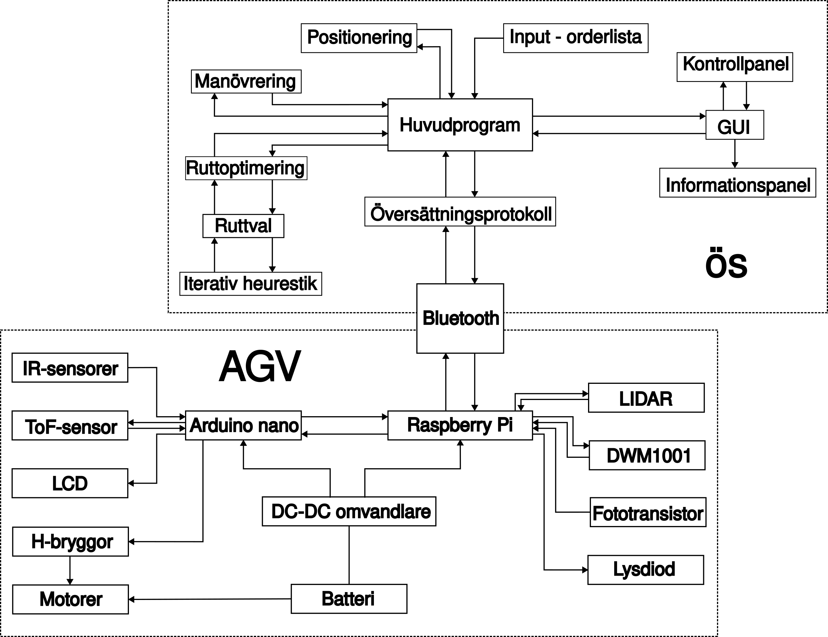
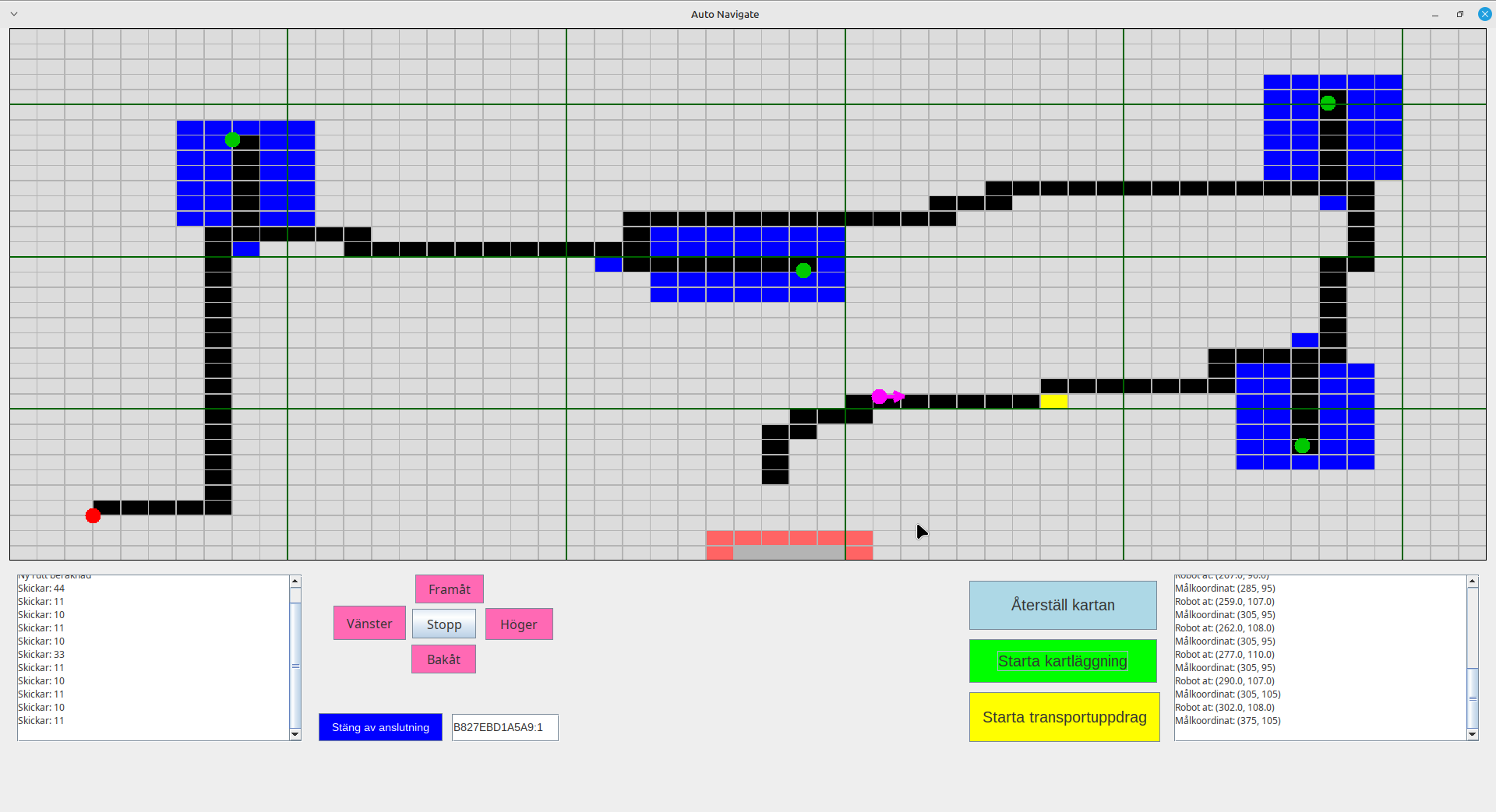
The AGV and ÖS talk over Bluetooth using a small command protocol: ÖS sends single- or double-digit drive commands (forward, backward, turn left/right by a fixed angle, stop, a "go to goal" command carrying target coordinates) and the AGV replies with an acknowledgement plus its current position, heading, and a full 360-value LIDAR distance sweep. ÖS uses that sweep to place obstacles and buffer zones on its map and re-plans with Dijkstra's algorithm whenever one blocks the current route; the AGV, meanwhile, autonomously handles the last stretch into each visit point using its own local sensors rather than being steered in by ÖS the whole way — see Heading and target-point docking below.
Physically the vehicle is split into three tiers: batteries and long cabling on the bottom, the two custom PCBs and microcontrollers on the main deck, and the LIDAR and UWB positioning module up top, clear of obstructions. Four wheels are driven differentially in left/right pairs.
Hardware
Two PCBs were designed for the project. An H-bridge board (two per side, driven by N- and P-channel MOSFETs) gives independent forward/reverse control over each side's motor pair for differential steering. A second board carries an LM2596-based buck converter that steps the 7.2 V battery down to a stable 5 V for the Raspberry Pi and other 5 V logic — a linear regulator was tried first but dropped for its poor efficiency once the switching design was in hand. Sensing is split across four devices: a 2D LIDAR (12 m range, 10 Hz rotation, 0.72° angular resolution) mounted vertically for obstacle mapping, two downward-facing IR reflectance sensors for following black tape strips near a target, a VL53L0X time-of-flight sensor on the front for close-range stop detection, and a phototransistor paired with an LED for confirming arrival at a target station.
Embedded software
Control is split across two processors in a small hierarchy: a Raspberry Pi 3B+ handles the heavier, non-time-critical work — sensor fusion, Bluetooth, positioning — while an Arduino Nano Every, wired to the Pi over USB/UART, handles low-latency motor and sensor I/O (H-bridges, IR sensors, the ToF sensor, and a status LCD). The two exchange plain-text line commands over a serial connection: the Pi sends drive/turn commands and periodic status strings, the Arduino executes them directly against the hardware.
Raspberry Pi
The Pi side is three cooperating Python processes plus one C++ one, all launched and supervised from a single main.py:
main.py— the main control loop. Reads Bluetooth commands and DWM position updates non-blockingly (selecton each subprocess's stdout), tracks current/desired heading, and both drives the AGV directly (forward/backward/turn commands relayed straight to the Arduino) and runs target-point docking once ÖS hands off a goal.DWM.py— talks to the DWM1001 ultra-wideband positioning module over a serial shell, joining its UWB network and configuring it as a position tag, then streams raw x/y/z measurements through an unscented Kalman filter (via FilterPy) to smooth out the millimeter-scale but noisy raw readings.bt.py— the Bluetooth link to ÖS, running in its own process and exchanging commands/telemetry withmain.pyover pipes.- A small C++ program built against the LIDAR's SDK (the only non-Python piece, since the SDK itself is C++) initializes the LIDAR's serial link, spins up its scan motor, and streams angle/distance pairs out for
main.pyto read and act on for obstacle avoidance.
Heading and target-point docking
The AGV has no compass — heading is inferred by comparing DWM position samples taken before and after a turn, using the vehicle's roughly constant 90°/s turn rate to time how long to hold a turn command for a requested angle. Positioning noise was the project's biggest recurring problem: raw DWM readings drifted enough while the AGV was moving that dead-reckoned position/heading estimates weren't reliable at cruising speed, which is why the vehicle periodically stops and averages several readings (the calibrationBudget-sample loop in main.py) before committing to a heading correction — accurate at the cost of top speed.
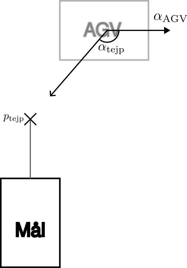
The last stretch into each visit point is handled locally rather than by ÖS: on receiving a "go to goal" command with target coordinates and approach heading, the AGV computes where a strip of tape leading up to the target should end, turns to face that point, and creeps forward. From there the two IR sensors correct heading if the AGV drifts off the tape strip, and the front ToF sensor detects arrival once the target is within about 6 cm. On arrival the AGV stops, flashes its LED, and rotates slowly back and forth until the target station's phototransistor sees it — at which point it signals ÖS that the visit is complete and resumes taking drive commands.
Arduino
The Nano Every owns everything that needs a fast, deterministic response: it drives the H-bridges from the drive/turn commands it receives over serial, reads the IR and ToF sensors and reports their state back, and continuously refreshes an I2C LCD with status messages (boot progress, Bluetooth connection state, live x/y position and heading during a run at 10 Hz, and shutdown status) so the vehicle's state is visible without a laptop attached.
Results
The final AGV met nearly every base requirement in the specification: autonomous start-to-finish navigation, sub-10 cm positioning via the DWM1001, obstacle detection and avoidance, LED-based arrival signaling, and status display were all delivered and demonstrated. The one requirement not met was the combined mapping-plus-delivery time target of 1–10 minutes — the DWM1001's positioning noise while the vehicle was in motion meant we had to trade speed for reliability, slowing down and adding periodic stop-and-average calibration stops to keep heading estimates usable, which pushed total run time over budget.
Conclusion
The project's biggest lesson was how much a supposedly centimeter-accurate positioning module (DWM1001) degrades under motion, and how much downstream design — heading estimation, docking, even overall run time — ends up shaped by working around that rather than the nominal spec sheet. Splitting control between a Raspberry Pi and an Arduino worked well in practice: the Pi was free to run heavier Python logic and juggle three subprocesses while the Arduino gave fast, unblockable response on the motor and sensor side. If I were to revisit it, the positioning pipeline is the first thing I'd improve — likely by fusing DWM readings with LIDAR-based scan matching instead of relying on periodic stop-and-average calibration alone.